| CFD Studio |
||||||||||||||||||||||||||||||||||||||
|---|---|---|---|---|---|---|---|---|---|---|---|---|---|---|---|---|---|---|---|---|---|---|---|---|---|---|---|---|---|---|---|---|---|---|---|---|---|---|
| |
Manual: |
|||||||||||||||||||||||||||||||||||||
| Boundary Conditions | ||||||||||||||||||||||||||||||||||||||
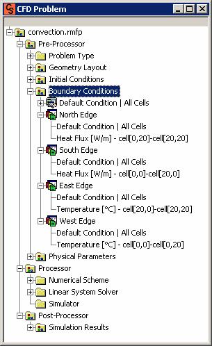
| In the Boundary Conditions module it is applied the physical conditions in the 4 boundaries of the geometry: North, South, East and West (Figure 1). | ||||||||||||||||||||||||||||||||||||||
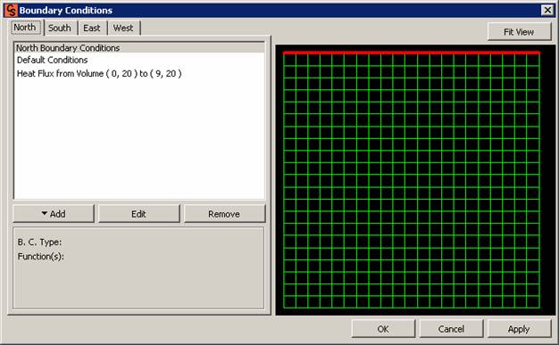 Figure 1- Boundary Conditions Setup. |
||||||||||||||||||||||||||||||||||||||
| The possible conditions are: prescribed temperature, prescribed heat flux, convection, prescribed velocities (u and v), outlet, symmetry condition and wall condition (Figure 2). | ||||||||||||||||||||||||||||||||||||||
 Figure 2 – Boundary Conditions Setup – Add options. |
||||||||||||||||||||||||||||||||||||||
Notice that for pure fluid flow problems the temperature, heat flux and convection conditions are disabled since the problem type just uses the momentum equations (Figure 3). |
||||||||||||||||||||||||||||||||||||||
 Figure 3 – Boundary Conditions Setup. |
||||||||||||||||||||||||||||||||||||||
When selecting the temperature, heat flux or velocities (u or v) conditions, it is first chosen the function type (Figure 4), then the function coefficients and finally, the boundary limits where the condition applies (Figure 5). |
||||||||||||||||||||||||||||||||||||||
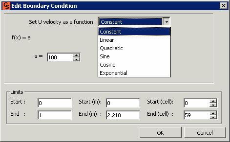 Figure 4 – Boundary Conditions Edit Window – function select (Temperature, heat flux or velocities u and v).  Figure 5 – Edit Boundary Condition Window (Temperature, heat flux or velocities u or v) |
||||||||||||||||||||||||||||||||||||||
In the outlet, wall or symmetry boundary conditions it is just informed the boundary limits that will receive that condition (Figure 6). |
||||||||||||||||||||||||||||||||||||||
 Figure 6 – Edit Boundary Condition Window (Outlet, open wall, wall or symmetry conditions). |
||||||||||||||||||||||||||||||||||||||
OBS: You must be careful in adding a boundary condition, since there is an overlapped criteria (because they use the same equation - in the same domain). In the table below are separate the conditions that can be overlapped relative to each equation (ie.: for the momentum equation in x the symmetry condition is overlapped for the inlet condition - respecting the addition order in the list Box of the window). |
||||||||||||||||||||||||||||||||||||||
|
||||||||||||||||||||||||||||||||||||||
| Button FIT VIEW, when clicked on the mesh image is automatically adjusted in the view screen (if the same is moved – Figure 7 and 8). | ||||||||||||||||||||||||||||||||||||||
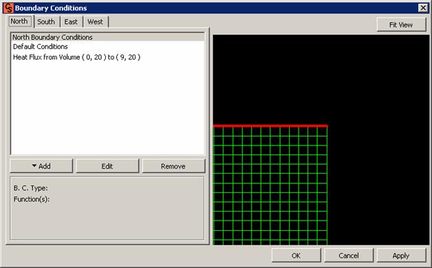 Figure 7 – Boundary Conditions Setup – Button FIT VIEW using. |
||||||||||||||||||||||||||||||||||||||
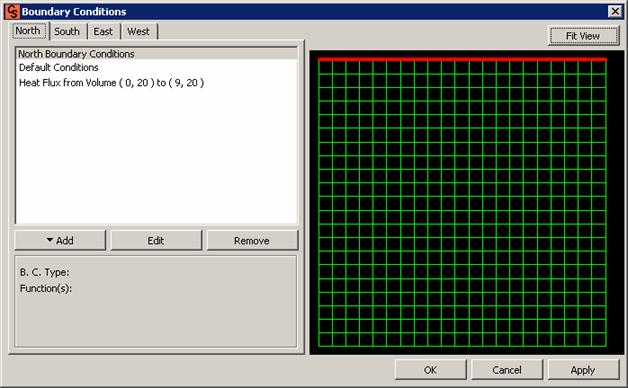 Figure 8 – Boundary Conditions Setup – Button FIT VIEW. |
||||||||||||||||||||||||||||||||||||||
| Always remember to click APPLY for the modifications to have effect in the problem parameters (Figure 9). | ||||||||||||||||||||||||||||||||||||||
|
||||||||||||||||||||||||||||||||||||||
| © SINMEC/EMC/UFSC, 2001. | All rights reserved. |