| |
CFD Grid Editor
|
 |
File Menu |
| |
|
|
| |
|
Opening a New Grid File |
| |
|
PATH: On the FILE menu, click OPEN, as in the Figure 1.
|
| |
|
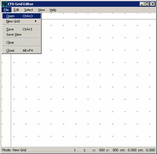
Figure 1
|
| |
|
In the new window (Figure 2), select name and the file type.
Ex: File Name: geometry.sdf
      File Mask: File SDF –2D Geometry (*.sdf)
|
| |
|

Figure 2
|
| |
|
Generating a New Grid |
| |
|
The Grid Editor 2D, besides the grids you can create in other grid generators and open with extensions “*.sdf”, it offer 8 different grid types (Figure 3).
|
| |
|
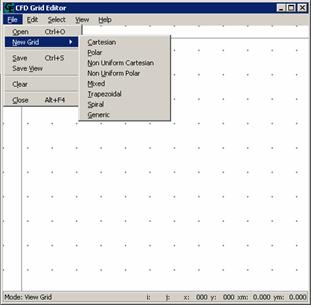
Figure 3
|
| |
|
Cartesian Grid |
| |
|
PATH: On the FILE menu, click NEW GRID, and choose CARTESIAN. Set height and width and the number of control volumes in each direction. An inclination can be given to the grid by setting a value for angle.
|
| |
|
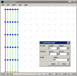
Figure 4
|
| |
|
Polar Grid |
| |
|
PATH: On the FILE menu, click NEW GRID, and choose POLAR. The polar grid is shown in Fig.5.
The internal and external radio and the angle of the geometry needed to be given.
|
| |
|
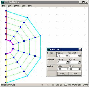
Figure 5
|
| |
|
Non-Uniform Cartesian Grid |
| |
|
PATH: On the FILE menu, click NEW GRID, and choose NON-UNIFORM CARTESIAN GRID.
The grid stretching is given by an equation of the type AX2s+BX+C, where the coefficients A, B and C are constant values.
|
| |
|
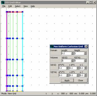
Figure 6
|
| |
|
Non-Uniform Polar Grids |
| |
|
PATH: On the FILE menu, click NEW GRID, and choose the NON-UNIFORM POLAR GRID option.
An example of a Non-Uniform Polar Grid can be seen in Figure 7. Again the equation AX2+BX+C, governs the coordinate distribution. Remember that if you do not have enough Ksi lines, a circular geometry will be not well represented.
|
| |
|
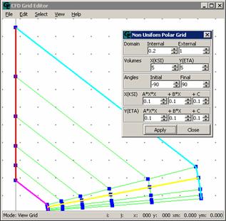
Figure 7
|
| |
|
Mixed Grid |
| |
|
PATH: On the FILE menu, click NEW GRID, and choose the option MIXED.
The Mixed Grid, as it can be seen in the Figure 8, mix Cartesian with polar grids. Dimensions can be changed in the MIXED GRID window (Figure 8).
|
| |
|
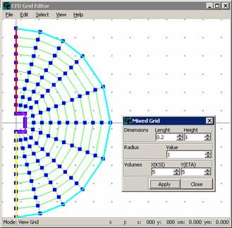 Figure 8
|
| |
|
Trapezoidal Grid |
| |
|
PATH: ON the FILE menu, click NEW GRID, and choose the TRAPEZOIDAL option.
The Trapezoidal Grid, as it can be seen in the Figure 9, is defined by four grid points Southwest, Southeast, Northwest and Northeast, whose values (X, Y) need to be given, as is shown in Figure 9.
|
| |
|
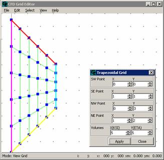 Figure 9
|
| |
|
Spiral Grid |
| |
|
PATH: On the FILE menu, click NEW GRID, and choose SPIRAL option.
To create a spiral grid (Figure 10) you need to define the initial and final radius and angles and the number of volumes.
|
| |
|
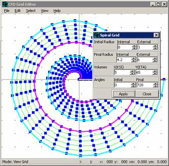 Figure 10
|
| |
|
Generic Grid |
| |
|
PATH: On the FILE menu, click NEW GRID, and choose the GENERIC option.
The Generic Grid can be used when there is the need to publish points separately and to move points in any direction. For that it is firstly necessary to locate the node (nodes position) that one wants to move, altering X (KSI -SN value) and Y (ETA -WE), in the window GENERIC GRID (Figure 11) and soon after, to move the node in relation to the length and height.
|
| |
|
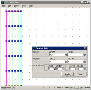 Figure 11
|
| |
|
How to Save a Grid |
| |
|
PATH: On the FILE menu, clicks SAVE.
To save a grid created with the Grid Editor, follow as indicated in Figure 12.
|
| |
|
 Figure 12
|
| |
|
Doing this the window (Figure 13) will be open. In this window, the folder should be specified. Do not forget the .sdf file type.
|
| |
|
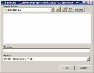 Figure 13
|
| |
|
How to Save an Image |
| |
|
PATH: On the FILE menu, click SAVE VIEW.
To save the image of the Grid Editor screen, follow as indicated in Figure 14.
|
| |
|
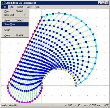 Figure 14
|
| |
|
The window (Figure 15) will be open. In this window, the folder should be specified. Do not forget the termination “.bmp"ou " or “.tif ".
|
| |
|
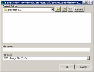 Figure 15
|
| |
|
Cleaning Screen |
| |
|
PATH: On the FILE menu, click CLEAR, as in Figure 16. This command allows the user to clear the screen and to start a new work.
|
| |
|
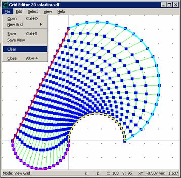 Figure 16
|
| |
|
Ending the Session |
| |
|
PATH: On the FILE menu, click EXIT. Follow as in Fig. 17.
|
| |
|
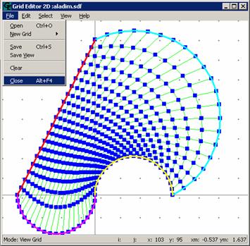
Figura 17
|