| |
CFD Grid Editor
|
 |
Edit Menu |
| |
 |
Moving Grid Nodes |
| |
|
PATH: On the EDIT menu, click MOVE SELECTION, as in Figure 19.
To move one or more grid nodes, select the nodes to be moved. To select them, see in SELECT NODES of the MENU SELECT.
|
| |
|
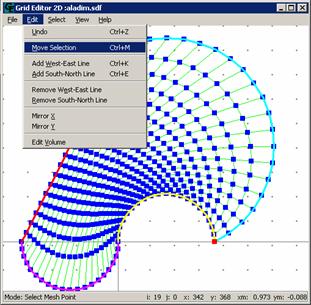
Figure 19
|
| |
|
To move a specific node, after having selected, just click on it and drag it to the required position, as in Figure 20.
|
| |
|
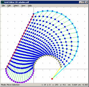 Figure 20
|
| |
|
To move a group of grid nodes, select them and drag them until the required direction. (Noticed that the group of nodes keeps its original layout, as in Figure 21.
|
| |
|
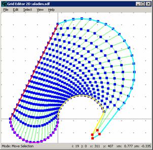 Figure 21
|
| |
|
Remember not to cross the coordinate lines when moving nodes, since the resulting grid is not accepted by the numerical method (Figure 22).
|
| |
|
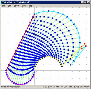 Figure 22
|
| |
|
Adding Grid Lines |
| |
|
It is possible to add (Eta-WE) and the (Ksi -SN) lines. The lines (Eta -WE) cross the domain from west to east while the (Ksi-SN) cross the domain from south to north, and this nomenclature will be kept to remember the user that the ETA lines are lines of constant values of Eta. The same applies for Ksi.
PATH: To add new (Ksi -SN) lines, on the EDIT menu, click ADD LINES SOUTH TO NORTH. See Figure 23.
|
| |
|
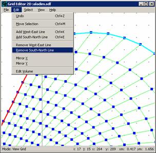 Figure 23
|
| |
|
Click now in the position where the new (Ksi-SN) line should be added, as in Figure 24.
|
| |
|
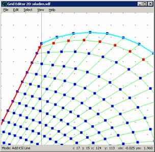 Figure 24
|
| |
|
It is also possible to add new (Eta-WE) lines.
PATH: to add new lines (Eta-WE), on the EDIT menu, click ADD LINE WEST-EAST (Figure 25).
|
| |
|
 Figure 25
|
| |
|
Click now where the new (Eta-WE) line should be added. See Figure 26.
|
| |
|
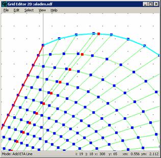 Figure 26
|
| |
|
Deleting ETA lines |
| |
|
PATH: To delete a line (Eta -WE), on the EDIT menu, click DELETE LINE WEST-EAST. After selection it will appear in the left bottom corner in the screen, Mode: Delete a ETA line. Select them the line that needs to be removed, clicking with the left button of the mouse in one of the line nodes. In Figure 28 a (Eta -WE) line that was in the initial grid represented by Figure 27 was deleted.
Notice that the line will only be deleted if the pointer of the mouse is exactly on one of the nodes of the line.
|
| |
|
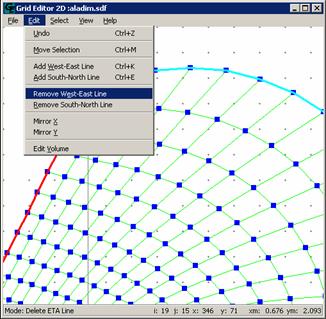 Figure 27
|
| |
|
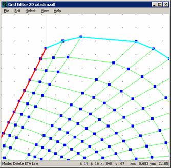 Figure 28
|
| |
|
Deleting KSI Lines |
| |
|
PATH: To delete a (Ksi-SN) line, on the EDIT menu, click DELETE LINE (Ksi-SN).
After selecting this function it will appear in the left bottom corner in the screen Mode: Delete KSI Line. Repeat the same as for removing ETA lines. In Figure 30 a (Eta-WE) line that was in the initial grid shown in Figure 29 was deleted.
|
| |
|
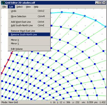 Figure 29
|
| |
|
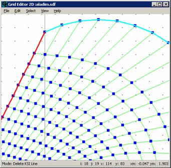 Figure 30
|
| |
|
Mirror in X |
| |
|
PATH: To realize this function, on the EDIT menu, click MIRROR IN X. The grid will be automatically reflected in X. Figure 32 shows the grid of Figure 31 reflected in X.
|
| |
|
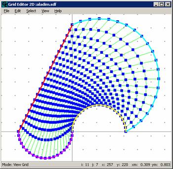 Figure 31
|
| |
|
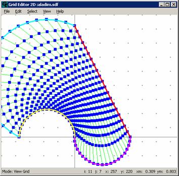 Figure 32
|
| |
|
Mirror in Y |
| |
|
PATH: To realize this function, on the EDIT menu, click MIRROR IN Y. The grid will be automatically reflected in Y. Figure 34 shows the grid of Figure 33 reflected in Y.
|
| |
|
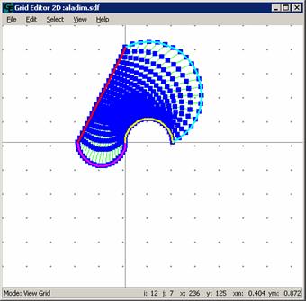 Figure 33
|
| |
|
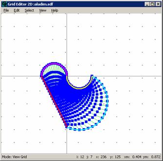 Figure 34
|
| |
|
Edit Volume |
| |
|
PATH: To execute this function, on the EDIT menu, click EDIT VOLUME.
The execution of this function makes to appear in the screen a window VOLUME; this window is related with the edition of the volumes (or elementary cells in 2D). For that, just select an elementary cell clicking inside of the grid. The coordinates of the points (North-NW, South-SW, East-SE, West-SW) can be changed.
In the window Volume it is informed the (I,J) location of the volume, the coordinates of its center and its area. In the following illustrations you can see an example of a volume modification in a generic grid. First, the edit volume window is opened (Figure 35).
|
| |
|
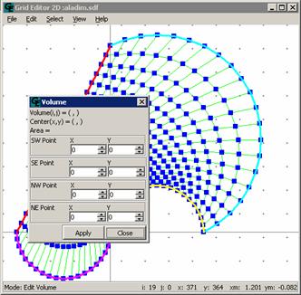 Figure 35
|
| |
|
Then a volume on the grid is selected with a click on the left button of the mouse (Figure 36).
|
| |
|
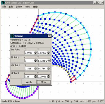 Figure 36
|
| |
|
Now the values are changed in the Volume window. The resulting grid can be seen in Figure 37.
|
| |
|
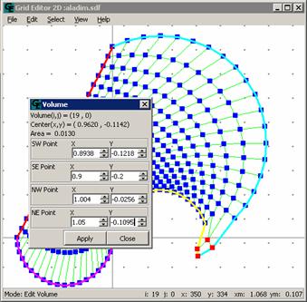 Figure 37
|
| |
|
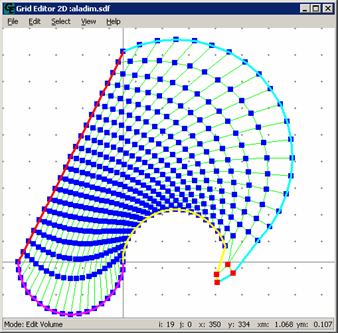
Figure 38
|